Beginning Machining
- 2s982mit
- Mar 17, 2021
- 3 min read
Updated: Mar 18, 2021
This week, our team was able to start machining parts for our mill! We machined the carriage platform and the threadless nut, and look forward to more productive machining in the future.
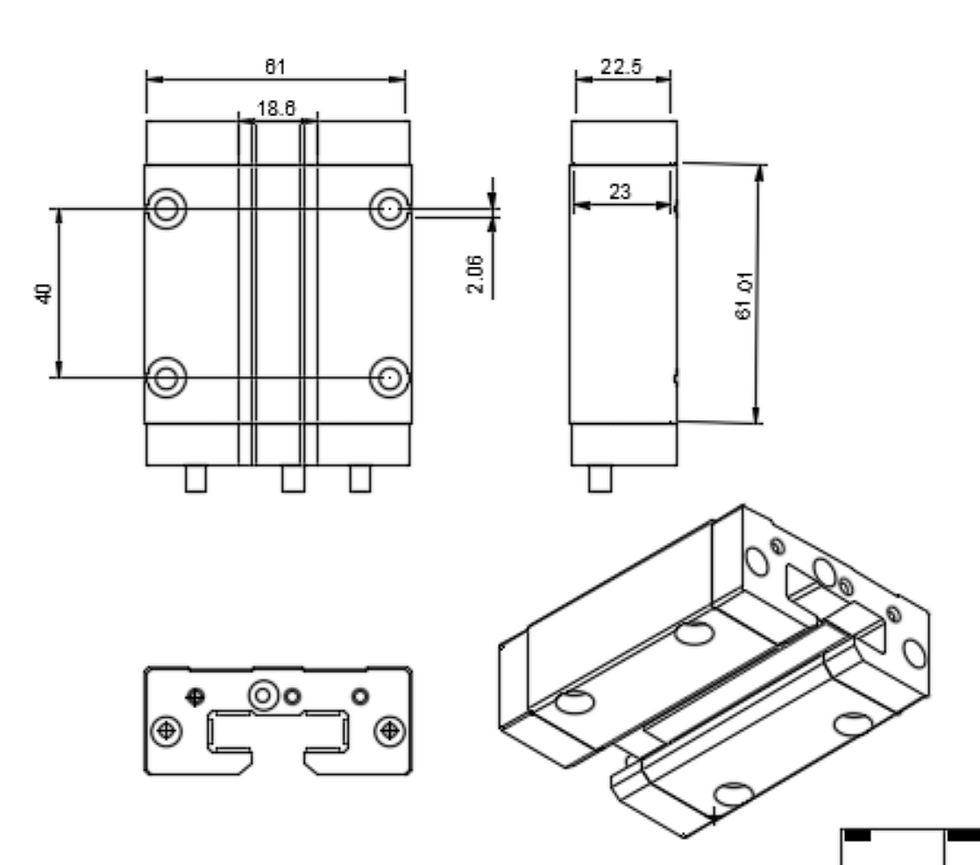
The first sub-assembly we will focus on is the system for the X-directional axis movements.

We also created engineering drawings for the various parts of the sub-assembly, to aide in machining next lab. With the drawings, we can easily determine dimensions, holes, and more.


Updates on the Threadless Leadscrew
This week I used my lab's MarkForge 3D printer to make a demo threadless leadscrew to verify my design before making it out of aluminum. And boy am I glad that I did! I made the nut with a pitch of 5 degrees, resulting in a desired lead of 0.1374 in using a 0.5in rod as the 'screw'.
I brought the printed nut to LMP and tapped all of the appropriate holes and added the bearings. I realized my first mistake with the design in that I made clearance for the the shoulder bolts a little too short, so I had to increase the hole by hand and accidentally ruined a few of the tapped holes. Therefore I wasn't able to secure the bearings on one side properly. To avoid this mistake on the other side, I attempted to use oversized nuts as spacers and I was able to tighten the bolts to secure the bearings on the other side. However, in this case the bearing wasn't able to spin properly! I think I should get some washers that are properly sized to raise the inner race of the bearings so that the bearing can rotate. I believe that will fix the issue.
The second issue I noticed was regarding the preload method. In my initial design I made a simple slit in the side with a threaded hole on one side and a clearance hole on the other. When a bolt is passed through the hole and tightened, the sides of the nut are brought together and tightened. After having used this method with the 3D printed nut, I think it will be too difficult to apply a known preload in this method. The two sections of the nut separated by the preload-slit are too stiff and very difficult to tighten. I will modify this for the next iteration of the design.
When I did some simple testing, I measured the lead of the nut assembly to be approximately 0.1in, which I believe is pretty darn close to the expected 0.1374 in. lead. Particularly since I used very rough measurement methods (pencil and sharpie).
If we have a desired lead of 0.01in, for a 0.5in diameter shaft the required pitch angle is 0.365 degrees. If we make the spacing of the bearings for a shaft of 0.25 in, we can achieve a lead of 0.01in with a pitch of 0.729 deg, which may be easier to achieve. With this we should be able to achieve fairly accurate motion. Even by hand, if we can add a handle that that will allow for adjustments of 36 degrees per 'click' (10 'clicks' per turn), we can achieve a resolution of 0.001 in. Using a stepper motor we can achieve much higher resolution.
However, I would much rather use a thicker shaft to counter against buckling. If we use a steel shaft we shouldn't have a problem, especially if we preload the shaft properly. However if we don't mount the shaft properly it would be best practice to make the shaft thicker. If we did this, I am unsure if we can achieve the required pitch angle (0.3 deg). If we can make this angle then no problem! Definitely worth a discussion.
Therefore, the main changes I made to the nut design after experimenting with the 3D printed part are:
Changed pitch angle to 0.729 deg
Change desired shaft size to 0.25in
Change preload method from diagonal slit to sawing block in half for addition of preload springs
-RMHB


Comments