Major Mill Decisions
- 2s982mit
- Mar 2, 2021
- 3 min read
After a great first lab, our team met up to discuss our week 2 deliverables, and make the key decisions about our mill design.
Our first task was to determine the configuration of our axes.
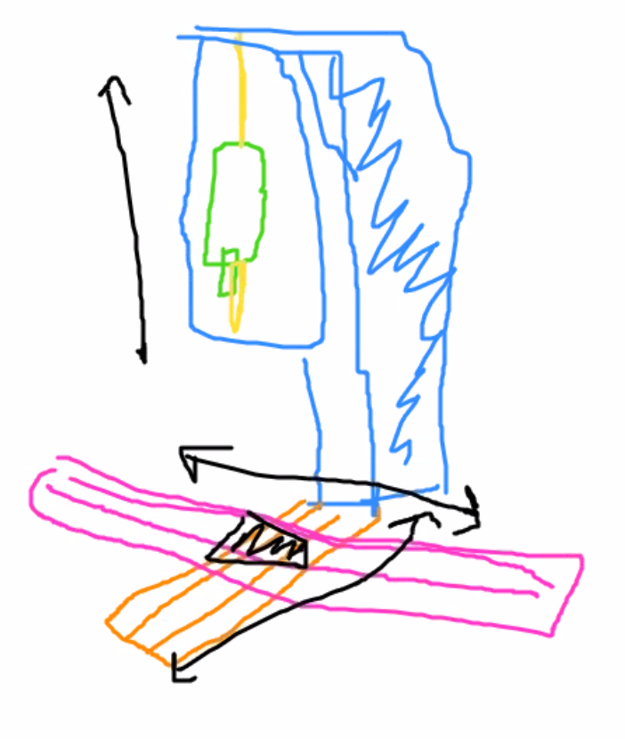
We quickly decided that our table would move in the X-Y plane, and our spindle would move in the Z axis. We were inspired by Paul's mill-in-progress in LMP, and his choices of axes. We also chose for our spindle to move in the Z axis, and not the table, as it would require less strength to set up a part.

We next decided upon using threadless nuts for our axes drivers. This was less motivated by any technical considerations or mechanical analysis, but rather, just because our team found them quite interesting and wanted to experiment with something new. We also chose a simpler mill configuration in order to dedicate more time to extra features, such as the novel threadless nuts.
For our axis guides, we decided on using t-rails linear guides since they have more or less uniform stiffness, and higher area moment of inertia, so they are better than circular shaft type rails. We’ll be buying the rails since they are easily accessible, and not super expensive (there are expensive ones too, but for our purposes cheaper ones are fine).
We could design a good linear guide mechanism using the two circular rods for guides, but the stiffness varies depending on where the carriage is along the length of the rail. Using T linear guide rails we avoid that issue and we have a guide rail profile that is stiffer by default. We can buy the rail and carriages from VXB or McMaster.

We will have the spindle attached to the z axis and the z-axis will need to be bolted to a big beefy ‘arm’, like the cast iron structure of the bridgeports or Haas. This may be slight overkill but our team member had been burned by the engraving routers from 2.72 last year, and would rather have a machine that can handle higher cutting forces than one that can’t.
The x and y axes will be bolted together at right angles, similar to the bridgeport. It will take some significant calibration and clever precision design to make sure that the axes are perfectly perpendicular throughout the length of their travel. We can most likely use some techniques learned from Slocum to accomplish this (Kinematic coupling, elastic averaging pins and slots etc.)

Our first main challenge is to use threadless nuts as our drive mechanism. We have never used or designed this type of mechanism before and we expect it to require rigorous testing and validation. Our second main challenge is that we would like to have our machine be able to be used by hand or by cnc. This will involve choosing either appropriate motors that can be back-driven or developing a mechanism that will detach the motor from the drive mechanism. Further, we must use additional encoders attached to the linear drive to measure the absolute position of each axis regardless of drive method. We can measure the position by either measuring the rotation of the drive axis (threadless nut axis) or by perhaps having a belt drive attached to the carriage whose sole purpose is to measure carriage location.
Our third challenge is that we would like to incorporate the (optional?) use of a 4th axis. Ideally the 4th axis could be removed and replaced with a simple vice if not needed. We have never used a 4th axis to machine a part before, so it will be fun to design parts that will be made using all of the available axes.


Comments